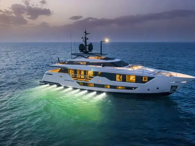

$11,490,000
OFFERED BY
Allied Marine Brokerage and Charter
LOCATION
Miami, Florida United States of America
YEAR
2023
LENGTH
106.0 ft.
Condition
Used
Name
CIAO M
Year
2023
Make & Model
Custom Line 106
Boat type
Power
Length
106.0 ft.
Location
Miami, Florida United States of America
Beam
24.25 ft.
Cabins
5
Draft
6.66 ft.
This stunning 2023 Custom Line 106 is a masterpiece of Italian design and engineering. With only 80 engine hours and never having been used, this yacht is in pristine, like-new condition. It offers unparalleled luxury, cutting-edge technology, and exceptional performance, making it the ultimate choice for discerning yacht owners.
Located in Miami, FL, this vessel is ready for immediate delivery. The full warranty ensures peace of mind, covering all aspects of this magnificent yacht.
Key Features:
This is an extraordinary opportunity to own an almost brand-new Custom Line 106 without the wait. Priced competitively at $11,399,000, this yacht is a rare find and won’t be on the market for long.
Hull and StructureHULL GENERAL
Hull form is designed on the basis of experience on previous similar Yachts, taking into account resistance, seakeeping and maneuverability characteristics.
The structural design and assessment is designated according to the most recent experience acquired by the Builder in design and construction of GRP for this type of Yacht and according to the RINA Classification Rules. The hull is divided into 3 watertight compartments, by the watertight collision bulkhead on the forepeak and watertight Engine room bulkhead, in accordance with Classification rules. The watertight collision bulkhead is positioned in accordance with the Classification Rules. A chain locker space suitable to contain both port and starboard chain cables are provided forward the watertight collision bulkhead.
HULL & DECK MATERIALS AND CONSTRUCTION
The Yacht has been constructed with a combination of sandwich and single skin GRP laminate using mat, unidirectional/biaxial E-glass/carbon fibers and closed-cell foam cores for sandwich, according to the structural drawings approved by the Classification Rules. A skin coat is made using vinylester resin to prevent osmosis of the inner laminate. Hull (both bottom and sides) and deck is made (mainly) of sandwich laminate by infusion process.
The hull structure is framed with main longitudinal structural members and transversal bulkheads, and secondary transversal structural members.
Fuel oil and black, grey, fresh water tanks will be integrated. Each tank have at least one manhole. Internal tank surfaces will be treated using vinylester resin as follows:
• Fuel tanks: 2 C-glass layers
• Fresh water: food grade gelcoat
• Other tanks: 2 additional E-glass layers
The deck structure is made of longitudinal/transversal structural members and sup- ported by bulkheads.
Bulkheads are made of GRP sandwich and composite marine plywood. GRP bulwark is integrated into the hull sides.
The bulwark is equipped with fairleads, access doors and freeing ports, in compliance with the Classification Rules. A GRP bow thruster tunnel has been installed on the hull by proper lamination as well as watertight connections through watertight bulkheads.
STRUCTURAL REINFORCEMENT, PLATES AND INSERTS
Fore and aft ends
Main machinery foundations
Shaft brackets
Rudders trunks
Stabilizers machinery
Bow-thruster tunnel
Sea chests
Hull transducers
Windlasses
Bollards
Anchor hawses
Tender and water toys launching and haulage system
Shell door kinematics
Cranes or heavy lifting machineries foundations
Brass or equivalent inserts are fitted to distribute concentrated stress due to the fastening of heavy machinery and parts to the hull structure (eg. hand rails, pillars,…). Hawse piping is made by GRP laminate. Installations are in compliance with the Classification Rules, where applicable.
HULL SHELL DOORS
The Yacht is equipped with the DMT (Dual Mode Transom) system, a patent by Ferretti Group. The transom door is able to open in two alternative modes:
By turning down (Beach Area mode) thus creating a large bathing platform with natural teak laid.
By turning up (Float-in Garage mode) thus allowing the launch/haul of the tender or toys.
Both the movements are associated with the lowering of the central portion of the aft platform.
The whole kinematics is electro/hydraulically operated.
On the forward garage an hinged shell door are installed opening upward and electrohydraulically actuated.
The design and installation is in compliance with the Classification Rules.
MACHINERY AND EQUIPMENT FOUNDATIONS
Marine plywood, epoxy fiberglass sheets (GPO3), brass and steel inserts, integrated to the Builder discretion, are provided as machinery and equipment supports.
Aluminum structural frames dedicated to the gensets are installed.
The engine room and control room floor are made in knurled aluminum and sup- ported by aluminum profiles frame.
SUPERSTRUCTURE MATERIALS AND CONSTRUCTION
The superstructure are constructed with a combination of sandwich and single skin GRP laminate by infusion process using mat, unidirectional/biaxial E-glass/carbon fibers and closed-cell foam cores for sandwich according to the structural drawings approved by the Classification Rules. The structural frame is made of main longitudinal and secondary transversal structural members, using carbon fibers on specific areas.
HARD TOP
The hardtop and lateral supports are made composite structure and supported also by pillars at forward and aft ends. The hardtop includes:
Painted mast in welded aluminum alloy structure with radars, lightning. conductor, navigation lights, and sensors.
Navigation and communication equipment.
PAINTING AND FINISHING
All the products used for the painting ARE standard finishing suitable for this type of Yacht. The Yacht has been delivered with a premium quality, industry recognized marine coating.
EXTERNAL FINISHING
The quality of polished gelcoat parts finishing is defined by builder quality standards and control procedures. The finishing is white gelcoat except beauty line and other parts.
The yacht external surfaces are finished according the different zones; each zone is characterized by its own quality levels and checks. In general the acceptance criteria involves fairness, cracks, gloss, orange peel. Antiskid areas are in accordance with the related plan, and and antifouling paint is applied to the underwater portion of the hull.
AFT AND FORWARD GARAGES
Aft garage has gelcoat finish except for the ceiling where wood has been installed. Forward garage walls and ceilings have gelcoat finish.
BOW THRUSTER SPACE
The bow thruster space is closed by a bolted metallic panel.
ENGINE ROOM
The engine room walls are covered with aluminum/rubber sandwich plate and ceiling with Di Bond or similar metal sheeting. The paneling is smooth white finish easy to clean and presents a hard abrasion resistant surface inside the machinery spaces.
AISI 304 handrails are fitted around the engines and along stairways or where deemed necessary for safety reasons. Handrails is dismountable.
ENGINE CONTROL ROOM
The control room is located aft of the engine room. A watertight hinged door gives access to the engine room. The flooring is aluminum plate. The room is well lit, and fitted with air conditioning.
CATHODIC PROTECTION
Dedicated anodes for hull, shafts, propellers, rudders, thrusters and stabilizer fins .
HULL GRIDS
The main sea intakes is equipped with fixed grids.
TRANSMISSIONS
The main engine is directly coupled with the gearbox;. the propulsion assembly (main engine and gear box) is elastically supported on resilient mounts.
MAIN ENGINES
Two four stroke diesel engines suitable for marine propulsion are installed on foundations in the engine room, one on each side:
Manufacturer: MTU
Model: 16v 2000 M96L
Rated power (each): 2638 mhp / 1939 kW @ 2450 RPM.
Rated power is according with the manufacture operating profile 1DS (average power: less than 60% of rated power / annual usage: up to 1000 hours). Exhaust emissions in compliance with IMO II / EPA TIER 3 regulations.
GEAR BOXES
Each engine has a reduction gear box ZF 3070A. Reduction ratio determined on relation to the propeller design and propulsion set is 2.750:1.
SHAFT LINES, BEARINGS AND SEALS
Sea water lubricated bearings are installed for each propulsion shaft line. Shaft material is made of Marinox17.
Mechanical seals are mounted inside the hull, they are cooled by the seawater system.
On the propeller side each shaft is supported by one custom designed single strut, constructed in NiBrAl and designed according to the Classification Rules. The support is completed by a bossing in heavy thickness tube. A hydro-lubricated rubber bearing is fitted into the bossing.
PROPELLERS
Two skewed propellers, 5 blades, diameter about 1250mm, designed to obtain high efficiency and low noise will be provided. They are made by nickel- aluminum-bronze (NiBrAl). Each propeller is statically and dynamically balanced. Manufacturing tolerances will be according to ISO 484/2 CLASS S.
RUDDERS
Two spade rudders with drive by wire steering control are installed. The blade size is determined to ensure good maneuvering capabilities; the rudder is properly transversally off-set from shaft line axis in order to remove the screw shaft without dismounting the blade. The rudders construction material is AISI 316L. Rudder holes are in stainless steel, rudder stock is made of Marinox17.
STEERING
The steering system is of electrohydraulic type. A drive by wire steering wheel are fitted in the wheelhouse and on the Fly helm station. On the dashboard a control panel shows the main info (mode, alarm status, rudder angle) of the steering system. The hydraulic system is made of one power pack (oil reservoir with a 400V/50Hz/3ph pump) and 2 hydraulic cylinders (one for each rudder).
BOW THRUSTER
A bow thruster unit driven by a 58Hp hydraulic motor is installed in a dedicated space. The installation is executed strictly according to Manufacturer instructions and specifications. Control Joystick are installed on both wheelhouse main and fly helm stations.
STABILIZER FINS
Two electro hydraulic stabilizer fins working underway and at zero speed have been installed. The fins control is integrated in the main dashboard with additional control panel for backup in wheel house.
INTERCEPTORS
Two units, one for each side, is installed on the transom edge actuated by servo units connected with control units. The system is governed by the monitoring system in the wheelhouse.
ELECTRIC POWER GENSETS
Two diesel generators with the following characteristics are installed in the engine room:
• Manufacturer Kohler
• Rated power outputs: 44kW
• Rated voltage / frequency and phases: 400Vac/50Hz – 3 phase
• RPM 1500
• Insulation class: H
• Tension regulation: ±0.5 %
• Frequency regulation: ±0.5 %
• Starting system: 24 Vdc
Each diesel genset is provided with automatic shut-down for the following alarms:
• Low oil pressure
• High water temperature
• Overspeed
Each diesel genset is equipped with:
• Sound-proof enclosure and white paint RAL according to the Maker's standard.
• Resilient support system.
• Built-in freshwater circulating and cooling system with heat exchanger
• oil cooler.
• Electronic speed regulators.
• Control panel installed outside the soundbox equipped with:
– Starting/stop push buttons
– Volts, amps and hour meters
Exhaust gas system are wet type, with a gas water separator and outlet installed on the hull side shell at waterline level; pipes to gas/water separator and between gas/water separator and outboard are in CuNi. The gensets installation is done strictly according to Manufacturer instructions and specifications.
BILGE AND FIRE FIGHTING SYSTEM
Each watertight compartment has a separate bilge suction, with foot valve, connected through the main bilge manifold to the bilge pump.
Water from the bilge discharged overboard through an overboard connection located in the engine room. Main engines cooling pumps can be used to draw water from the engine room bilge in case of emergency.
Second bilge suction on each watertight compartment, with foot valve, connected through the emergency bilge manifold, to the emergency bilge/fire pump and discharging overboard through a three way valve. The emergency bilge manifold has been installed out of the engine room. Where drainage is not necessary, the arrangements may be omitted provided that yacht safety will not be impaired.
Chain locker is self draining, additionally one bilge suction connected to a dedicated hand pump has been installed. A bilge alarm system, connected to the alarm and monitoring system, has also been installed in all compartments served by the bilge system. The bilge pumps can be started and stopped from the control panel.
Bilge lines have flexible hoses fire resistance (ISO 7840) inside machinery spaces while fire resistant (ISO-13363) hoses outside machinery spaces; the manifolds are made in AISI 316 stainless steel.
FIRE FIGHTING SYSTEM
This system has its own pump in the engine room and is connected to the bilge system in such a way that the bilge and fire fighting pumps may serve as bilge pumps and vice-versa.
Fire hydrant valves, with fire hoses and nozzles are fitted, in the following positions:
• n°1 on sun deck
• n°2 on main deck
• n°4 on the lower deck
Equipped with fire hoses not longer than 18m and nozzles having a diameter of 12mm of dual-purpose type (i.e. spray/jet type).
The chain washing system is made by two nozzles installed on each hawse pipe, connected to the fire-fighting piping. The washing facility is activated from the wheelhouse or locally by a remote control temporized valve.
Fire-fighting lines piping material is flexible fire resistant according to ISO 15540/1 inside ER or ISO 7840 outside ER.
BILGE PUMP
One electric self-priming centrifugal pump 400Vac/50Hz/3ph in the engine room for main bilge system with a drip tray. The pump can be by-passed with the electric fire pump.
FIRE FIGHTING PUMP
One electric self-priming centrifugal pump 400Vac/50Hz/ in the engine room for fire extinguishing system with a drip tray. The pump can be by-passed with the electric bilge pump.
EMERGENCY DIESEL MOTOR PUMP
One diesel motor pump with a flow rate of max 550 l/min and a manometric head of max 40m H2O is installed, in the control room.
FUEL OIL SYSTEM
One structural storage fuel oil tank and one structural daily tank is fitted in the hull bottom as per tanks capacity plan. Lines are installed in the engine room to transfer fuel from each tank to each other by two e/pumps. The valves are manually operated.
Filling stations located on main deck sides, one port and one starboard, and a able to deliver the fuel to bunker tank. The valves are manually operated.
Piping material flexible fire resistant according to ISO 15540/1 inside ER or ISO 7840 outside ER. Connections to main engines and generating sets are made with flexible pipes with oil resistant synthetic rubber.
FUEL OIL TRANSFER PUMP
The transfer system allows to transfer from each tank to each other by means of one 24Vdc pump and a second 400V/50Hz/3ph unit, both of them are provided with a drip tray. The pumps controls are located on the main electrical panel in engine control room and monitored in the main dashboard in wheelhouse. The two generators will be fed by one electrical booster pump each.
FUEL OIL FILTERS
Filters for main engines (duplex type) and diesel generators (single).
FRESH WATER SYSTEM
One fresh water tank on the hull bottom in the forward area as per tanks capacity plan. Cold and hot water lines are provided to feed the various users. The hot water is produced by two 220V/50Hz electric boilers of 100 litres of 1.5kW heating capacity each and distributed onboard by a ring, a circulating pump keeps the constant temperature.
Wash down shower connections, integrated into the fresh water system
Water supply for the wipers mounted in the wheelhouse.
Hot water pipes are insulated.
Filling lines on the aft main deck on both side.
FRESH WATER MAKER
One (1) single type reverse osmosis desalination with total capacity 180l/h, and feed water temperature of 25 °C. The water maker production is delivered directly into the tank, the unit is placed in the aft technical spaces, pre-mounted on a frame and completed by pre-filters, fresh water flushing and local control panel.
FRESH WATER PUMP
One water pressure system made by two electrical pumps supplied by 400Vac/50HZ/3ph in aft technical area.
SEWAGE SYSTEM
One black and one grey water structural tanks fitted according to tanks capacity plan; each system with dedicated piping. Two transfer self-priming pumps, one for each system, sucks from two manifolds and allows for discharging through two separated overboard connections. Discharge by means of one Marpol flange placed.
WC connected to the fresh water system for flushing; waters are delivered to the tank by their own pump. Overboard discharge of not treated sewage shall be executed when in compliance with International regulations as applicable.
Grey water system is designed to have sinks, baths and showers draining by gravity through conventional collection tanks equipped with automatic pump and connected to the tank. Washing machines and dishwashers discharge directly in the gray water tank. Galley users discharge directly into the tank by gravity. A three-way valve, properly labelled, in an accessible location for outboard discharge.
Piping material made by flexible and hard wall rubber hoses with metal helix for both black water and grey water systems.
BLACK AND GREY WATER PUMPS
One black and one grey water electrical pumps 400Vac/50Hz/3ph in the aft technical space.
FIRE EXTINGUISHING SYSTEM
ENGINE ROOM EXTINGUISHING SYSTEM
A fixed gas fire fighting system out of the engine room. A sound and visual alarm operating automatically when fire alarm is activated.
GARAGE EXTINGUISHING SYSTEM
The aft garage is equipped with a fire fighting sprinkler system fed by sea water.
COMPRESSED AIR SYSTEM
One electric driven compressor unit having a power requirement of about 1,5kW in the engine room able to deliver air at 7bar as maximum, together with a reservoir of approximately 24 litres. The system supplies compressed air to the horn as standard and through a pressure reducing valve to the connections in engine room, aft garage, beach area and fore deck.
SCUPPERS AND DRAINAGE SYSTEM
Scuppers and drainage system collect and discharge outboard the wash down and rain waters from external decks. Above freeboard deck, pipes are made of PVC (rigid) and flexible hoses. Below freeboard deck scupper lines are in flexible hoses in compliance with ISO 13363. On the external decks, scuppers are equipped with removable grills in stainless steel. The aft garage is drained by a manual 24VDC pump connected overboard.
SEA WATER COOLING SYSTEM
Used for cooling both the main engines, the gearboxes and the exhaust gases; there are two symmetrical systems able to be connected through a valve fitted on the manifold placed between the two sea chests (one dedicated to each side) and normally closed.
A dedicated sea chest for feeding the water maker.
Each shaft seal has an independent cooling piping system and is able to be connected to the cooling engine system of both starboard and port sides.
Each generator cooled through its own sea water system.
Piping material for sea water system made in CuNi 90-10. For main engines lines, flexible hoses in compliance with ISO 13363 used for gearbox, shaft line and generators lines. Connections to the engines is made by using flexible joint.
Sea chests listed below installed and close to each unit the related strain.
AIR VENT LINES
All structural tanks with adequate air vent line.
Fuel oil tanks vents connected to a single line, then led overboard through a goose neck placed above main deck. Material is the same used for the system. Fresh water vent line led to the hull overboard connection through a goose neck to be placed above main deck.
Black and grey water vent lines overboard through a goose neck to be placed above main deck.
Hull connections.
HYDRAULIC SYSTEM
The systems consist of the power packs feeding the following systems, where in-stalled:
Steering gear
Transom shell door and lift
Gangway
Stabilizers fins
Forward garage shell door
MAIN ENGINES GAS EXHAUST SYSTEM
The exhaust gas of each engine led mainly underwater and partially above the waterline through a GRP duct installed in each lateral sponson of the hull.
Metallic compensators at the engines gas outlets. Before entering the GRP duct at side, the gas cooled by sea water coming from the engine cooling system.
The main dry pipes in stainless steel AISI 304 while AISI 316L for the wetted parts. Sea water pipes in flexible hoses in compliance with ISO 13363.
AIR CONDITIONING SYSTEM
Designed and built in such a way as to guarantee comfort in weather conditions . Interior living spaces such as cabins, saloons, wheelhouse served by the air conditioning system. The yacht ventilation system is based on the following principles:
Living spaces, galley and wheelhouse.
Galley and bathrooms with mechanical air extraction.
Aft technical spaces and aft garage mechanically ventilated by extractor units and natural inlet.
Engine room mechanically ventilated.
Air conditioning and heating achieved through fan coil units.
ANCHOR AND MOORING EQUIPMENT
Two High Holding Power type anchors in galvanized steel in stainless steel anchor pockets. Each unit will weigh about 140kg connected to the hull through a chain 16mm in diameter made in galvanized steel, with stud link and having a length of 165m each.
MOORING BOLLARDS
Polished stainless steel AISI 316L bollards as follows:
• n. 4 on the forward maneuvering area mounted onto the deck (2 for each side)
• n. 4 on the aft raised mooring areas in the main deck cockpit (2 for each side)
• n. 4 horn type integrated in the fairleads, fitted on the main deck side bulwark (2 for each side)
• n. 2 on the aft platform (1 for each side)
FAIRLEAD
Polished stainless steel AISI 316L fairleads will be fitted in bulwark as follows:
• n. 2 on the forward maneuvering area, equipped with 3 vertical rollers each (1 for each side)
• n. 4 with integrated hooks, fitted on the side bulwark (2 for each side)
• n. 2 on the aft bulwark in way of the raised mooring area equipped with 3 vertical rollers each (1 for each side)
WINDLASSES
Two electrical windlasses vertical type (5.5kW, 400VAC/50Hz/3ph), dual rotation on the foredeck, bolted to the deck and locally controlled by means of a controller. Each windlass equipped by a stainless steel gypsy, one stainless steel drum and mounted close to a chain roller mounted on top of each hawse pipe. A polished stainless steel plate below the windlasses to protect the gelcoat and facilitate the removal of dirt.
CAPSTANS
Two foot switch electric operated vertical capstans (2.2kW, 400VAC/50Hz/3ph) on the raised mooring area built on each side of the main deck cockpit. Each unit provided by dual rotation at single speed.
FENDERS AND WHIPS
8 cylindrical and 6 ball fenders with covers completed with 3m of docking line
3 boat hooks (2 x 4.0m + 1 x 3.0m
One set (opt) of mooring whips (2 units) for the tender
DOCKING LINES
A total of 130m Ø26mm black docking.
GANGWAY
A retractable electro-hydraulic gangway with polished steel frame, planks teak laid and a manually removable handrail on the aft port side of the yacht. The walking width of the smallest part about 500mm and the reach from aft end of the hull about 1800mm. Vertical angle will be +/- 10 deg. The walkway has courtesy lights. Safety working load of such gangway 150kg. The control panel will be close to cockpit entrance with buttons of man present type. A receiver is fitted for remote control.
SWIMMING LADDER
Portable polished stainless steel foldable swimming ladder, with teak steps manually installed by using two sockets fitted in the aft platform by means of polished stainless steel flanges.
AFT GARAGE AND TENDER
Fitted for accommodating one tender (Owner's supply) equipped with diesel propulsion system having a power lower than 200kW.
An electro-hydraulic actuated DMT shell door at stern made in GRP and opens in two modes, upward (Float-in Garage mode) and downward (Beach Area mode). On the whole the use of the shell doors is limited to calm sea and sheltered waters. The status of the shell doors is monitored through the central monitoring system. The operation of the DMT door is by means of a local control panel.
Hydraulic winch to haul out and launch the tender on the rollers fixed on the garage floor.
Lights fed by 230Vac and emergency 24Vdc power supply on the ceiling.
Watertight hinged door to separate the garage from adjacent compart- ments.
FORWARD GARAGE
A storage with hydraulic hatch, at bow under the forward deck sunpad
GLASS WINDOWS
The type and thickness of the glazed panels are in compliance with Regulatory Bodies requirements.
Windows are Grey Europe colour (except for the wheelhouse) and are fitted on the hull and superstructures as per GA and exterior design.
PORTHOLES
Polished stainless steel portholes with Grey Europe glass in the lower deck crew area as with a round shape.
WATERTIGHT DOORS
One between engine control room and engine room
One between the aft technical space and the engine room
One between engine control room and garage
BULWARK DOORS AND AFT GATES
Two gates at main deck level, on the stairs leading to the bathing platform, hinged type, with a polished stainless steel frame.
Two bulwark doors (one on each side) with concealed hinges and stainless steel threshold and locks.
EXTERIOR DOORS AND HATCHES
Main deck aft salon to cockpit: glazing door, sliding and rotating type, painted frame, made in 3 parts, manually operated sliding.
Main deck pantry area (port side): manual pantograph door with grp structure.
Main deck access to control room (port side): manual pantograph door made in GRP.
Main deck lobby (starboard side): glazing door, sliding type, with painted frame made in 2 parts, 1 sliding manually actuated and 1 fixed.
Sun deck: two manual pantograph doors, made in GRP with glazed opening with electric lock/unlock system.
Wheelhouse to sun deck: glazing hatch, sliding type with painted frame, made in 1 sliding manually operated part.
Manually operated weathertight hatches with sensor for monitoring their status on the deck in the following areas:
• Emergency escape from engine room, flush type sill
• Fore peak access, flush type sill
• Emergency escape from the owner's cabin, flush type sill
• Sun deck escape from fore crew cabin through horizontally hinged hatch.
HANDRAILS, CAPRAILS, PILLARS AND EXTERNAL NON STRUCTURAL STAIRS
Polished stainless steel AISI 316L handrails, on the following areas:
Handrails specifically designed by the shipyard and the designer on the lateral bulwark opening on both stbd and port sides on main deck.
SD aft perimeter: 60x20 mm rectangular section polished stainless steel handrail with black painted stanchions (circular section D32mm) and rails.
SD lateral and fore perimeter: black painted stanchions and synthetic rope rails.
Non structural stairs with stainless steel supporting frame and steps covered by teak planks.
Two painted or polished stainless steel pillars on the sun deck for supporting the hard top.
TEAK DECK LINING
The main and lateral/fore sun external decks planked with natural teak and black caulking as standard, including deck hatches.
Bathing platform and transom door planked with natural teak and black caulking.
Planks size 45mm wide and max length of 3000mm, 12mm thick. Teak planks glued directly on the decks using vacuum system lay.
SAFETY EQUIPMENT
Housed life buoys (2) with light and smoke
2 Life rafts for 10 people each (total 20 people)
20 Life jackets
• 2 Child life jackets
• 1 SART Transponder
• 1 EPIRB
The list of the standard fire fighting appliances is the following:
• Foam extinguishers (3)
• Powder extinguishers 1Kg (2)
• Powder extinguishers 6Kg (5)
• CO2 extinguishers 5Kg (6)
• Fire blanket (5)
TENDER CRADLES
One set of plastic rollers for the tender inside the aft garage mounted on stainless steel frames bolted to the bottom plate.
SIDE TRACKWAYS
Working tracks above windows on full beam sections of the superstructure to allow windows cleaning by the crew using a harness and bosun’s chair.
Two sliders (cars) and end stops to each rail.
FLAGPOLES
Stainless steel flag pole on the aft bulwark on the sun deck.
WINDOW WIPERS
The front wheelhouse windows equipped with three windscreen wipers with both intermittent and variable speed control
Cold water cleaning jets
EXTERIOR SHOWERS
One shower handset, with wandering connection on the stern swimming platform
POWER DISTRIBUTION
The system is designed to ensure that load is evenly distributed over the three phases.
The ac power sources are connected to the main switchboard installed in the control room with automatic magneto thermic circuit breaker and remotely controlled too.
A source back-lit push buttons for every power to show to on-line/off-line status together with lamps for indication line voltage.
An emergency stop button for each generator on the main switchboard 400 and 230Vac bus bars divided into two sections, each section feeds half of the users.
A bus tie splits the two bus bar systems, manually operated and allows to connect one or two generators to the distribution system.
Dedicated automatic protection devices that prevents mistakes in the electrical sources management operations. T
Grounding system is a separate neutral conductor (TN-S type).
Distribution system fitted with a low insulation indicator device providing alarm signal locally and to the monitoring system.
Reverse power protection system for each generator.
SHORE CONNECTION
Standard supply one 3 phase isolation transformer 70kVA, 400Vac input, 400/230Vac with neutral output.
One 125A socket with about 20m cable.
One electric device for handling the portable power cable at stern.
Converter 'on line' and 'off line' operations is executed only from the converter unit front panel.
MAIN SWITCHBOARD
Constructed (IP22) in steel, painted and installed in the engine control room. The front side isolated handrail natural ventilation grids and openable hinged panels.
Proper labels for each gauge or switch.
Bus bars of hard drawn copper, proper sized section and insulated.
All the lines coming from the switchboard pass through manually operated circuit breakers having short circuit and over current trips.
The switchboard is divided as follows:
• 400/230Vac Generators and shore line control panel
• 24Vdc power supply section
• Section for the various systems start switches
The generators panel section include the following main elements:
• One multimeter for each generator
• Volt gauges, amperage gauges
• Earthing control
• Mayer (SLS) system
• Overload alarm
• Signal lamps
The 24Vdc switchboard section accommodates the magneto thermic switches for dc electrical system users and the monitoring system display.
Each genset has an insulation switch and lights to indicate run and stop condition.
EMERGENCY SWITCHBOARD
Installed as near as is practicable to the emergency source of electrical power, fed by emergency battery system.
24Vdc battery bank equipped by a manual battery switch-off and a dedicated battery charger, and sized according to the electrical balance in emergency conditions and according to the Regulatory Bodies requirements.
DISTRIBUTION SWITCHBOARDS
The distribution boards are distributed along the Yacht according to the electrical system design, constructed in metallic or composite material and fed by the principal board by lines equipped with protection circuit breakers. The lines in departure are protected by manually operated circuit breakers.
BATTERIES
Two groups (24Vdc) (one per unit) for the start of the main engines; fed by a battery charger
Two groups (12Vdc) (one per unit) for the start of the diesel generators; fed by a battery charger
One group for the 24Vdc emergency distribution; fed by a battery charger
One group (24Vdc) for the radio station; fed by a battery charger
One group for the 24Vdc users (services); fed by a battery charger
Start batteries recharged by the alternators installed on the related engine and a dedicated battery charger.
Start batteries for the main engines can be swapped in case of emergency.
The status of all batteries will be shown on the central monitoring system.
ELECTRICAL MOTORS AND STARTERS
Each motor starter has insulation switch and lights to indicate run and stop condition.
LIGHTING SYSTEM
LED lighting n general interior accommodation areas . Main lighting system 230Vac through drivers electronically controlled and generally positioned in the distribution switchboard of the area. In black-out condition a few lights fed by the emergency batteries.
TECHNICAL SPACES
Technical spaces are illuminated according to the Builder’s standard by a 230Vac system through ceiling lights or bull eye type in smaller areas.
Large storage lockers with sufficient lighting supplied by 24Vdc line, with local switch.
The engine room and the control room are illuminated by means of IP55 ceiling lights with a switch in way of the main access.
WHEELHOUSE
Reading light at the chart position.
Red light lighting system in the wheelhouse for night navigation.
CREW AREAS
LED type spotlights in the ceiling of the crew accommodation.
Each crew bed is equipped with a LED reading light.
INTERIOR LIGHTING (VIP & BEACH CLUB)
The lighting in VIP areas and beach club is based on the installation of ceiling LED type spotlights and strip LED along the edges of the ceiling and in way of steps of internal stairways, as internal courtesy lights.
Each room has at least two distinct illumination systems with respective switches.
SWITCHES, SOCKET OUTLETS AND RELATED COVERS
Switches, 230Vac 3-pins 16A sockets and related covers manufactured by PLH, or similar, in VIP interior areas, crew areas, wheelhouse, pantry and Captain cabin sockets.
24Vdc, 230Vac and 400Vac sockets in engine control room, while in engine room one universal socket Vimar + GFI30mA.
EXTERIOR LIGHTING
The lighting system is designed to properly illuminate the decks, stairways and passageways, side boarding areas and the aft gangway.
Flood lights from the mast illuminate the port and starboard side.
Flood lights in the external edge of the deck ceiling illuminate the life raft boarding areas.
The anchor windlass on the foredeck illuminated by lights to allow safe working without glare.
All Exterior lights controlled from the wheelhouse
.Exterior lights:
• LED ceiling spots lights
• LED Floor spots lights
• LED Step lights for stairs
Including Required buffers, dimmers and power supply units/ transformers.
Exterior lighting will be from the Builder selection.
SEARCH LIGHT
One (1) search light on the mast and will be capable of being remotely operated from within the wheelhouse.
UNDERWATER LIGHTS
Underwater lights for illumination of the stretch of water around the Yacht. These are divided as follows: 8 on starboard side, 8 on portside and 4 on the transom. Underwater lights will be controlled from the wheelhouse and from the cockpit on the main deck.
EMERGENCY LIGHTS
All the passages and stairs leading to the Master station and other locations as required by the Regulatory Bodies will be equipped with a proper number of emergency lights.
The lights are fed by emergency battery bank or by an independent reserve power source.
FIXED FIRE DETECTION AND ALARM SYSTEM
Systemin all enclosed spaces, except those containing no significant fire risk (Toilets, bathroom, void space, etc) and manually operated call points placed through-out the yacht to ensure readily accessible means of notification, as required by Regulatory Bodies.
NAVIGATION SYSTEM
Innovative integrated dashboard with navigation and automation in the wheelhouse. The dashboard is composed by:
4 MFD 16” touch display (vertical)
2 MFD 16” touch display (horizontal)
2 jog system control
Bow thruster control lever
Main engines throttles
Main engines start/stop buttons and alarm signals + emergency stop buttons
Main engines key
Autopilot
2 VHF (class D DSC)
Alarm buzzers
The integrated dashboard allows the visualization and control (where indicated) of the following items:
Navigation Monitors configuration Management
Wheel House Device control scene Management
Language selector (Italian – English)
Integrated monitor brightness control (Hatteland)
Wiper control
Horn control
CCTV control
Search light control
Fog Horn signaling control
Wheelhouse light control
Navigation Light control
Heading
Roll & Pitch
Wind direction and speed
Sea depth
Yacht speed
Compass light control and dimmer
Steering control panel
Stabilizer System
Tank levels, including high and low level alarms
AC power page (main parameters of converter, shore power and generators where installed)
DC power page (main parameters of the main items fed by DC current)
Batteries
Main engines
Gearboxes
External doors and hatches and portholes (where applicable)
Shell doors
Internal watertight doors
Bilge Alarms
Fire detection system
Water maker
Bilge & fire pumps control
ER ventilation control
Vessel name (where back-lit)
Underwater lights control
External lights and cabin lights control
Rudder pump
Rudder position (RAI)
Steering mode and take over
Fire extinguishing
Engine Data Conning
Monitoring System
Additional stations:
Control stations positioned externally on sun deck and on the main deck aft cockpit, including the following commands:
Aft cockpit station:
– main engines throttles
– main engines control panels
– bow thruster control panel
Sun deck station (port or stbd):
– main engines throttles
– main engines control panels and indicators
– steering tiller and rudder angle indicator
– bow thruster control panel
– search light control panel
– autopilot
– Intercom, horn and VHF
NAVIGATION EQUIPMENT
1 magnetic compass with fluxgate overhead
1 autopilot, complete with gyro compass
1 echo-sounder with LCD color display
1 multifunctional transducer (depth, speed, temperature)
Navigation sensors including:
– n.1 radar 3,5ft , open array radar antenna
– n.3 GPS
– n.1 Flux gate system
– n.1 magnetic compass
– n.1 Weather station
NAVIGATION LIGHTS
1 white, masthead, navigation light.
1 white, anchor light.
1 red, port navigation light.
1 green, stbd navigation light.
1 white, stern lights.
4 red, not under command lights.
The navigation lights are controlled by a panel installed in the wheelhouse.
Audible and visual alarm to indicate failure of any navigation light.
Panel powered by the emergency system.
HORN
One (1) air horn.
Air pressure type with solenoid valve connected to the main air pressure system with local air receiver complete with control panel with fog signal timer installed on the bridge.
MONITORING SYSTEM
n.1 mfd display in main helm (16”).
n.1 mfd display in the crew mess (16”).
n.1 mfd display in the engine control room (16”).
COMMUNICATION SYSTEM
2 VHF radiotelephones with DSC GMDSS class D with 2 remote handsets in Crew Dinette and ECR.
2 portable VHF GMDSS apparatus.
1 radiotelephone SSB GMDSS – DSC.
1 NAVTEX receiver.
1 EPIRB 406MHz, GMDSS, with hydrostatic release.
1 radar transponder, GMDSS (SART).
NETWORK SYSTEM
LAN network and a dedicated WIFI network for on board information technology services, on board entertainment and AV system compatible with latest protocols and technology available at the time of installation of the equipment.
INTERCOM SYSTEM
An intercom system fed by the emergency supply line d in the following locations:
• 1 Central station with microphone in the wheelhouse.
• 1 Talk back station with headphones in the engine room at the local engine control post.
• 1 Talk back station at bow mooring post.
• 1 Talk back station at stern mooring post.
CCTV SYSTEM
n.3 fixed type, 2 in the engine room, 1 in engine control.
n.3 waterproof fixed camera, 2 on the ceiling of the external main deck corridor (one for each side), 1 in main deck cockpit
Cameras be placed for best view and so that normal lighting does not blind the cameras.
System integrated with the monitoring system.
ENTERTAINMENT SYSTEM AND IT
(AV) system with centrally installed media server, satellite receiver and other necessary equipment Luxury and crew areas have LED TV’s and appropriate sound systems.
(1) Omnidirectional land antenna with TV, AM/FM.
Standard cabling for an integrated system in all areas.
Centralized entertainment system with a main rack unit placed in a dedicated area.
LOWER DECK AND GUEST AREA
Lobby
Staircase MD – LD
Port Guest cabin (aft) with wardrobe
Port Guest bathroom with separated wc and bidet
Stbd Guest cabin (aft) with wardrobe
Stbd Guest bathroom with separated wc and bidet
Port Guest cabin (fwd) with wardrobe
Port Guest bathroom with wc and bidet
Stbd Guest cabin (fwd) with wardrobe
Stbd Guest bathroom with wc and bidet
MAIN DECK
Main salon
Lobby
Staircase MD-UD
Day toilette
Port side Pantry
Galley and storage room
Crew corridor
Owner’s cabin
Owner’s study
Owner’s walking closet
Owner’s bathroom
UPPER DECK
Wheelhouse
CREW AREA (5 CREW)
Staircase
Crew dinette (stbd side)
ort side Captain cabin
Fwd port and starboard side crew cabins (double)
APPLIANCES
Galley:
Electric glass/ceramic 5 burners cooking top BOSCH
Hood (30 a.c./h)
Oven (90cm / 35,4inc.) BOSCH
Dishwasher (12 people) BOSCH
Fridge side-by-side BOSCH
Trash compactor
Double sink
Pantry Main Deck:
Microwave oven
Fridge undertop BOSCH
Crew mess:
Microwave oven
Fridge undertop
Laundry (crew area):
Dryer BOSCH
Washer BOSCH
Sun Deck:
Drawer bottle fridge 90l
Icemaker
Grill
ENGINE 1
Engine Manufacturer
MTU
Engine Model
M96L 16V
Fuel Type
Diesel
Horse Power
2000.00
Max Speed Knots
26
Cruising Speed Knots
22
Hours
80.00
Location
Port
Engine Range Nautical Miles
400
ENGINE 2
Engine Manufacturer
MTU
Engine Model
M96L 16V
Fuel Type
Diesel
Horse Power
2000.00
Max Speed Knots
26
Cruising Speed Knots
22
Hours
80.00
Location
Starboard
Engine Range Nautical Miles
400
HULL
Hull Material
fiberglass
ACCOMMODATION
Crew Cabins
3
OTHER
Country Built
Marshall Islands
Displacement(kgs)
321875
Fuel Capacity Gal
3884
Fuel Tanks Capacity
14702.53 liters
Gross Tonnage
210
No of Heads
6
Water Capacity Gal
793
Water Tanks Capacity
3001.83 liters
The Custom Line 106 is 110 feet long and has a 24 feet beam and can hold up to 3884 gallons of fuel and 793 gallons of water. This Custom Line 106 is powered by MTU M96L 16V with 2000.00 horsepower and is capable of reaching a maximum speed of 26 knots and a cruising speed of 22 knots.. The Custom Line 106 is made of fiberglass.
$8,200,000
LENGTH:
108.01 ft.
|
YEAR:
2016
LOCATION:
Ft. Lauderdale, Florida
OFFERED BY:
Allied Marine Brokerage and Charter
$15,995,000
LENGTH:
108.23 ft.
|
YEAR:
2024
LOCATION:
Fort Lauderdale, Florida
OFFERED BY:
Allied Marine Brokerage and Charter
$13,995,000
LENGTH:
103.51 ft.
|
YEAR:
2017
LOCATION:
Palm Beach, Florida
OFFERED BY:
Allied Marine Brokerage and Charter

$10,990,000
LENGTH:
108.99 ft.
|
YEAR:
2020
LOCATION:
Fort Lauderdale, Florida
OFFERED BY:
Allied Marine Brokerage and Charter
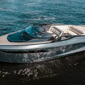
$570,000
LENGTH:
114.83 ft.
|
YEAR:
2022
LOCATION:
Fort Lauderdale, Florida
OFFERED BY:
Allied Marine Brokerage and Charter

$10,495,000
LENGTH:
110.01 ft.
|
YEAR:
2020
LOCATION:
Aventura, Florida
OFFERED BY:
Allied Marine Brokerage and Charter

$8,200,000
LENGTH:
108.01 ft.
|
YEAR:
2016
LOCATION:
Ft. Lauderdale, Florida
OFFERED BY:
Allied Marine Brokerage and Charter

$15,995,000
LENGTH:
108.23 ft.
|
YEAR:
2024
LOCATION:
Fort Lauderdale, Florida
OFFERED BY:
Allied Marine Brokerage and Charter
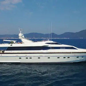
$2,599,000
LENGTH:
106.63 ft.
|
YEAR:
2001
LOCATION:
Fort Lauderdale, Florida
OFFERED BY:
Ocean Independence

P.O.A.
LENGTH:
105.91 ft.
|
YEAR:
2025
LOCATION:
Seattle, Washington
OFFERED BY:
Worth Avenue Yachts
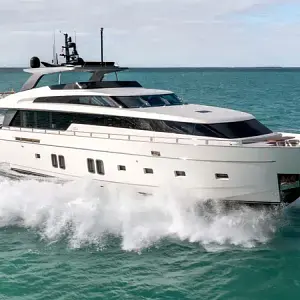
$8,450,000
LENGTH:
106.0 ft.
|
YEAR:
2019
LOCATION:
Miami Beach, FL
OFFERED BY:
Denison Yacht Sales

$13,995,000
LENGTH:
103.51 ft.
|
YEAR:
2017
LOCATION:
Palm Beach, Florida
OFFERED BY:
Allied Marine Brokerage and Charter

At our core, we love the sea and the ability to share our passion for it with you and your family. Our team is driven to deliver on a promise of providing an unparalleled yachting experience. We pride ourselves on integrity, passion and experience.